
Arducase
Project: Arducase
Backstory
Back in ~2016 when i was getting into home automation, I wanted to create my own devices. To that end I bought by first Arduino Kit on Amazon and had a fun few weeks learning all the pieces.
Once i learned i needed a Wifi chip for my goal, I bought two more boards and spent more time learning how to connect them. I ran into a roadblock when i hit something i didn’t know and wasn’t ready to dive into: MQTT
I kept everything I had but didn’t come up with another use case (pun intended) and the gear collected dust.
Build
It was now 2024 and I was finally doing some area beautification in my living room and determined it was time to do something with the Arduino gear.
Back to Basics
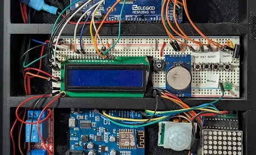
Connecting all of the sensors I’ve collected seemed both too easy and more difficult than I was interested in, and I wanted to use all the boards I had. I started by going back to basics with a single board and single sensor.
Once I had that going I moved on to communication. Getting them connected to Wifi felt familar as I worked through the last steps I had done before. Then I wanted to sync information, and it was back to MQTT.
Luckily, in my time since messing with these we have implemented MQTT at work and I’ve built a basic understanding of the Protocol now. We even looked into deploying MQTT into a K8s cluster, and I just so have to have recently migrated my home apps into a local K8s server.
MQTT
I chose to use EMQX for my MQTT setup because they publish a helm chart on artifact.io. It was easy to set up and ended up having built-in features I really liked.
Case
Now that I had working pieces, I needed something to put them in. My first Idea was a simple shadow box, but I had a coin display case that I had filled up and moved coins out of - and it happened to almost fit the breadboards perfectly.
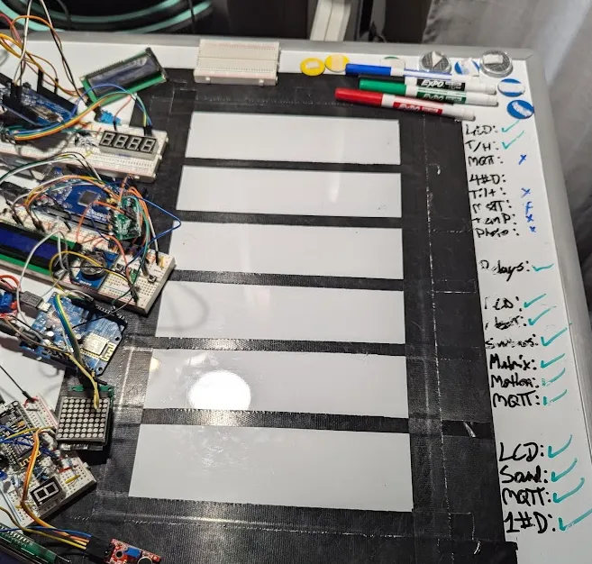
I started by taping the layout down on a magnetic white board. Then I used small magnets on all the gear so I could move the project space around fairly safely.
Then I began work on the power system. This is a bunch of Relays in parallel controlled by the central board. I tested connections and validated functionality of all the pieces.
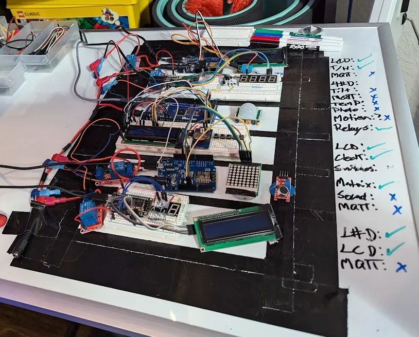
To stay in the case, everything needed to be able to somehow stick to the backing of the case. I cut adhesive velco pieces to fit all of the components. Again, i tested everything.
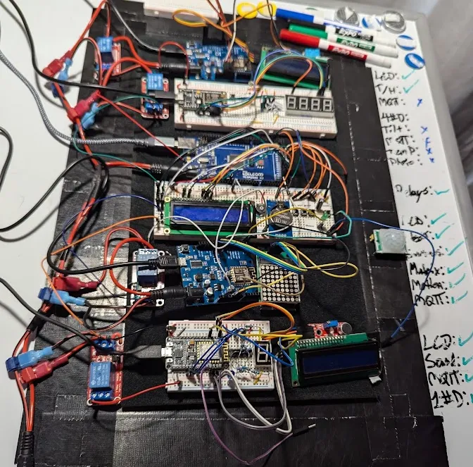
Once complete, I was able to slide the front of the case over the gear. The breadboards all had little tabs for connecting to each other that needed sanding off but then they were perfect.
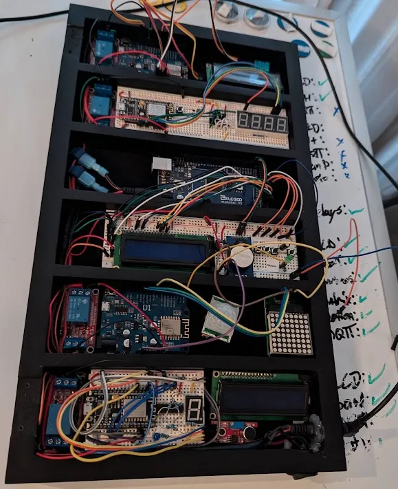
Then I tried my best to wire things nicely and gave it a test run.
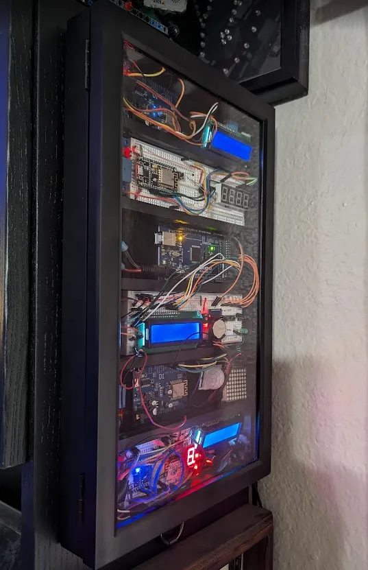
It worked very well, so I hung it up. It still needs a lot of work in the backend, but I think it looks cool.
← Back to blog